Don’t buy too Cheap, the different material of solar street light, choose good quality Solar LED Street Light
2452Don't buy too cheap, the different material of solar street light, choose good quality solar led street light
View detailsAbstract: Better thermal management allows LED luminaires to be driven at higher power levels while delivering stable light output and spectral quality over an extended lifespan. An LED heat sink is used to conduct heat away from the LED junction and then convect and radiate it to the surrounding environment.
An LED heat sink is a heat exchanger that absorbs thermal energy generated by an LED module and then dissipates the thermal energy into the surrounding ambient air. The heat sink is the last and most important part of the thermal path of an LED luminaire. The development of LED lighting technology is inextricably linked to the development of heat sinking technology. The spectral performance, lumen output and useful life (defined as 70% lumen maintenance) of an LED depend to a high degree upon the management of the LED junction level operating temperature. As LED technology pushes the boundaries of optical flux density, thermal management continues to pose a challenge for lighting manufacturers. Thus, as the primary system-level thermal management component the heat sink must be designed to unlock the full potential of LEDs, rather than being a thermal bottleneck.
Despite the breakthrough in luminous efficacy, LED lighting still experiences a substantial amount of energy loss in the course of AC-DC power conversion (driver circuit), electro-optical conversion (electroluminescense at the LED junction), and wavelength conversion (Stokes shift at the phosphor layer). Incandescent, florescent and metal halide lamps convert waste energy into various combinations of infrared radiation (IR), ultraviolet radiation (UV), and heat. As opposed to conventional technologies, all energy loss occurring during the light emission process of LEDs is discharged as heat. The system efficiency of most LED Products is less than 50%. This translates to a huge thermal engineering problem that more than 50% of the system power input is converted into package- and board-level heat.
LEDs have a junction temperature dependency of the forward voltage, spectral power distribution (SPD) and luminous flux (light output). The amount of light emitted by the LED drops as the junction temperature rises because the non-radiative recombination prevails at high junction temperatures. The increase in junction temperature will lead to a decrease in the bandgap energy of the active region of LEDs. This results in a reduction in forward voltage. Reduced forward voltage causes a decrease in the electrical power, which, combined with thermal droop, compounds the loss in light output. Thermally induced output drop is accompanied by the color shift. As the LED junction temperature rises, the bandgap between a conduction band and a valence band of the semiconductor layers becomes narrower. Since the wavelength of the electromagnetic radiation in the visible range is determined by the band gap, every 10ºC rise in junction temperature will result in one nanometer increase in the dominant wavelength of an LED. Consequently, there will be a noticeable color shift toward the higher end of the spectrum (yellow shift) when the LEDs operate at high temperature. Color shift also occurs at the phosphor layer when it is operated above the saturation flux level. Loss of phosphor quantum efficiency as a result of high Stokes heat leads to a blue shift.
High temperature operation within a limited period impairs the temporary efficiency and spectral quality of the LEDs. Operating LEDs continuously above the maximum allowed temperature at the p-n junction can lead to irreversible damage to the LEDs. The rate at which an LED will age is inversely proportional to the temperature at the p-n junction. Every 10ºC increase in junction temperature will results in a lifetime 30% to 50% drop in brightness. This permanent reduction in light output from the LED accelerated by a high operating temperature is known as lumen depreciation. Elevated temperatures will also accelerate degradation process of the polymer-based phosphor layer. Phosphor degradation and polymer carbonization end up in a color shift that cannot be tolerated in LED lighting. High junction temperature can cause a high coefficient of thermal expansion (CTE) mismatch between the LED die and packaging materials, which introduces a significant impact on the reliability of the LED.
As the majority of LED failure mechanisms are temperature-dependent, the semiconductor junction temperature must be kept low in order to ensure good performance and reliability. In general, the design of a thermal system includes consideration of the drive current, the ambient operating condition, the thermal resistances of all the components along the thermal path and all the associated interface resistances. Operating LEDs at high drive currents and high ambient temperatures without compromising light output and reliability requires efficient removal of heat from the semiconductor junction to the ambient environment. Heat always flows from higher temperature regions to lower temperature regions until a thermal equilibrium is reached. Thus, the task of thermal management is to reduce the thermal impedance of the lighting system. Thermal impedance is the measure of the total resistance to the flow of heat along a thermal path. It includes all the thermal resistance at component and interface levels.
A typical thermal design for an LED lighting system consists of package-level and system-level thermal management. Package-level thermal management handles the junction-to-substrate thermal resistance and thermal reliability of solder interconnection between the LEDs and the metal-core printed circuit board (MCPCB). System-level thermal management handles heat transfer from the MCPCB through a heat sink to the surrounding environment. To maximize the heat flow from the MCPCB to the heat sink, a thermal interface material (TIM), which can be a grease, epoxy or pad, is placed between the two components to fill in interfacial air gaps and voids. The role of the heat sink to extract the waste heat from the MCPCB as efficiently as possible to the ambient air so that no thermal buildup occurs within the LED packages. To do so the thermal transfer rates of the heat sink must outpace the load rate at which thermal energy is introduced to the junction.
There are three mechanisms that a heat sink employs for dissipating thermal energy from an LED system: conduction, convection, and radiation.
Thermal conduction is the transfer of heat by microscopic collisions of particles and movement of electrons between objects of differing kinetic energy. In addition to the ambient temperature, the removal of waste heat by thermal conduction is dependent upon the thermal conductivity of a material that the heat sink is made from and the geometry of the heat sink. Metals, metal alloys, some metal oxides, ceramics, diamond and other forms of carbon are good thermal conductors. Graphene, an allotrope of carbon in the form of a two-dimensional, atomic-scale, hexagonal lattice, has an astonishingly high thermal conductivity of 5000 W/mK. Among the metals, pure copper has the highest thermal conductivity (about 400 W/mK). Aluminum and its alloys have moderate thermal conductivities in the range of 90-240 W/mK. Ceramics, which’re both electrically isolating and thermally conductive, offer a thermal conductivity of between 100-200 W/mK. In LED lighting systems, conduction is the first mode of heat transfer along the thermal path. It starts at the semiconductor junction and the thermal load travels through a series of components to end at the convection surface of a heat sink.
Thermal convection is heat transfer by mass motion of a fluid, which can be either a liquid or, more typically, air. The movement of molecules within the convective medium of fluids takes place when there’s a temperature gradient between a solid surface and the fluid surrounding it or an artificially induced convection current. Convection is dependent upon the mobility of the fluid and the active surface area exposed to the flowing fluid. The mobility of the fluid is expressed by the heat transfer coefficient which is the proportionality constant between the heat flux and the thermodynamic driving force for the flow of heat. When the fluid motion is not generated by external source but by means of the buoyancy force induced by thermal gradients between the fluid and solid, the heat transfer is considered to be natural convection. In other words, natural convection utilizes the buoyancy force induced by thermal gradients between the fluid and solid. A heat sink operating in this mode is referred to as a passive heat sink, which has a heat transfer coefficient of between 5-20 W/m2 K. If a flow is created by means of external forces, the heat transfer is forced convection. Using an external force generated by fans, heat pipes, synthetic jets, or liquid cooling elements to increase heat transfer is called active cooling. With forced convection, the velocity of the air moving through a heat sink can be drastically increased above that of natural convection, with heat transfer coefficients in the range of 25 to 250 W/m2 K for air and 100 to 20,000 W/m2 K for liquids.
Thermal radiation refers to heat transfer through the absorption and emission of electromagnetic waves, without utilizing a carrier medium. The magnitude of radiative heat transfer has a very strong dependency on the emissivity and temperature of the surface material. Generally, non-metallic and non-transparent materials exhibit a high emissivity which typically exceeds 0.80. The emissivity of metals can vary between 0.02 (e.g. aluminum foil) and 0.90 (e.g. anodized aluminum) depending on the geometrical arrangement and surface treatment of the metal surface. A polished, shiny metal surfaces radiate very little heat. A painted or anodized surface radiates significantly more heat than a bright, unpainted one. The electromagnetic radiation rate of a material is proportional to its rate of absorption. Therefore, black colored surfaces that absorb more radiation than lighter colors such as white or metallic surfaces are more efficient in thermal heat transfer. The thermal energy transmitted through radiation increases steeply as the temperature rises. However, radiative heat dissipation at normal temperatures (0 – 100 °C) is generally negligible as compared to heat transfer by convection.
An LED heat sink is designed to first conduct heat away from the LED junction and then to convect and radiate heat to the ambient air. To fulfil the first role, the heat sink must be fabricated from a high thermal conductivity material to maximize heat transfer between the MCPCB and the exposed heat sink surface. As air is a poor thermal conductor, the heat trapped at the heat sink surface can only be dissipated via convection (and radiation depending on the type of luminaires and their applications). To accomplish the second task, the heat sink is required to have a sufficiently large enough surface area to convect heat away to the surrounding air. An aerodynamic design and/or a forced convection mechanism will be employed to ensure effective air circulation.
Radiation is hardly a contributing factor in thermal management for LED lamps (bulbs, tubes) and low-to-mid-power LED luminaires (downlights, ceiling lights, wall lamps, etc.) as its operation mechanism is high temperature dependent and requires a large surface area. Nevertheless, radiative heat dissipation can be employed to facilitate thermal management for high power LED luminaires which typically operate with a high case temperature and have a large heat sink. These LED luminaires include LED Street Light high bay lights, high power floodlights, and high mast lights. The heat sinks of these luminaires often receive surface treatments such as oxidizing, blacking or anodizing with the intention, which dramatically increases the emissivity of the heat sinks.
Heat sink design involves a system level trade-off as there’re many restrictions such as cost, space constraints, luminaire shape, manufacturability, and the air side conditions. Among all the heat transfer mechanisms, convection is a decisive factor in thermal management for LED lighting systems. With the advantages of a simple structure, low cost, high reliability and silent acoustics, passive cooling through natural convection is always preferred in LED system design. In most applications natural convection can be very effective and hence the term “LED heat sink” generally refers to the heat sink that relies on the thermodynamics of convection without an introduction of artificially induced force to enhance air circulation. Natural convection can be insufficient in some scenarios. Some types of LED luminaires, such as mogul-base lamps for industrial use in larger power ratings, have a small form factor but are required to produce a large lumen output. In this case, fan-assisted or other active cooling methods have to be used to increase the flow-dependent convection heat transfer coefficient.
Thermal conductivity of a heat sink is governed by its material composition, the conductive area, and the ambient temperature. Aluminum is the ubiquitous choice of material for LED heat sinks, despite the fact that copper has nearly twice the thermal conductivity of aluminum. In addition to its cost-effectiveness, moderately high thermal conductivity and high corrosion resistance, aluminum is also easily workable in mass volume using common casting, forging, extrusion and machining processes.
Aluminum heat sinks are not always made using the purest material. Aluminum alloys have been developed to address the processability issues or to enhance a specific characteristic, although the existence of most impurities will inevitably compromise the thermal conductivity. For example, magnesium is generally added the aluminum alloy for the purpose of increasing the tensile strength. The addition of copper can enhance the strength and thermal conductivity of the aluminum heat sink. Adding silicon enhances the fluidity of molten aluminum alloy at the time of die casting. A small amount of iron helps prevent dies from being fusion-bonded with the aluminum alloy.
Some heat sinks come with a ceramic or steel construction. Ceramics have thermal conductivities similar to aluminum and its alloys. What appeal to the lighting industry are their high dielectric constant and low manufacturing cost. The challenge of using ceramics is that they’re brittle and require extra handling precautions. Steel heat sinks are typically found on fixture-as-heat-sink LED lighting systems such as troffers and linear high bay fixtures. The housing of these fixtures are typically fabricated from die formed cold rolled steel. Stainless steel, which provides a very stylish aesthetic and is corrosion resistant, also finds its application in fixture-as-heat-sink lighting systems. However, both cold rolled steel sheets and stainless steel are less conductive than ceramic and aluminum (16-24 W/mK for stainless steel, 30-67 W/mK for carbon steel).
The convective removal of waste heat depends on the boundary conditions including, the effective surface area, the geometry of the heat sink, velocity of the air flow, and the orientation to gravity. The greater the surface area a heat sink has, the more convection occurs. For passive heat sinks to perform to their full capacity, it’s critical to maximize convection surface area. The design of a heat sink, however, is often limited by the size and shape of the lighting system. A passive heat sink commonly takes full advantage of the three-dimensional geometry to increase the convective heat transfer coefficient. Heat sinks typically come designed with fins to effectively increase surface area while allowing the heat sinks to remain confined to a given footprint. Fins are arranged in parallel to the airflow direction. The fin spacing is made to be sufficiently large in order not to stagnate or obstruct air flow.
Modern LED heat sink design has a trend toward a visually clean aesthetic and an aerodynamic design. Not only fin densities and depth are greatly reduced, an increasing number of designs seamlessly blend fins into the main metal structure to deliver a smooth minimalist appeal. The aerodynamic design allows a heat sink with low fin densities to capture as much airflow as possible. Some heat sinks that already come with an adequate surface area completely eliminate fins so as to resist dirt and dust deposits. Dirt and dust trapped in the pin or plate heat sink fins of conventional high bay lights and street lights are extremely difficult to clean. Accumulation of dirt and dust can significantly impair the convection and radiation efficiency of a heat sink.
The manufacturing process is an aspect of indispensability in the selection of thermally conductive materials and the design of heat sinks. Different processes can create different part geometry, render different thermal characteristics, and yield different mechanical properties. Heat sinks can nowadays be fabricated using variety of metal-forming approaches such as casting, forging, extrusion, machining, stamping, skiving, and bonding.
Die casting Aluminum heat sinks are made by forcing molten aluminum into a metal die which consists of two die halves locked and held together by hydraulic pressure. This process can produce aluminum heat sinks with highly complex shapes found in plastics while operating effectively in high ambient environments. Die castings are characterized by high dimensional accuracy and stability even with thin walls. Smooth or textured surfaces can be easily created and require a minimum of surface preparation prior to plating, coating or finishing. Die casting is the most efficient, cost-effective mass production process for LED heat sinks. It allows production of geometrically challenging finned heat sinks without compromising thermal integrity. Die castings have varied thermal conductivity depending on the compositions of aluminum alloys. ADC12, a silicon based alloy, has a thermal conductivity of 96 W/mk. Zi based alloys (e.g. Zamak 3) offer thermal conductivities in the range of 105-113 W/mK.
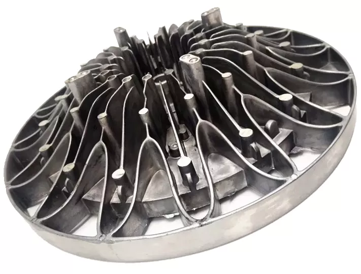
Cold forging is a metal-forming process by which a metal material is plastically deformed below its recrystallization temperature (usually at room temperature) under a massive application of pressure. Cold forgings win out in thermal conductivity, mechanical strength, dimensional accuracy, surface quality, manufacturing cost, and productivity over many other process. The process allows favorable crystal grain flow and thus results in improved thermal performance. Cold forged heat sinks typically yield a thermal performance improvement of up to 15% over the extruded heat sinks and up to 80% over the die cast heat sinks. With minimal resistance to deformation and high plasticity, aluminum and its alloys are well suited to this process. Cold forged heat sink using aluminum alloys in the 1000 range have thermal conductivities ranging from 220 W/mk to 240 W/mk. Cold forged 606x (e.g. AL6063) aluminum alloys have a typical thermal conductivity of 200 W/mk. The thermal conductivity of the cold forged 7xxx range varies between 115-222 W/mk.
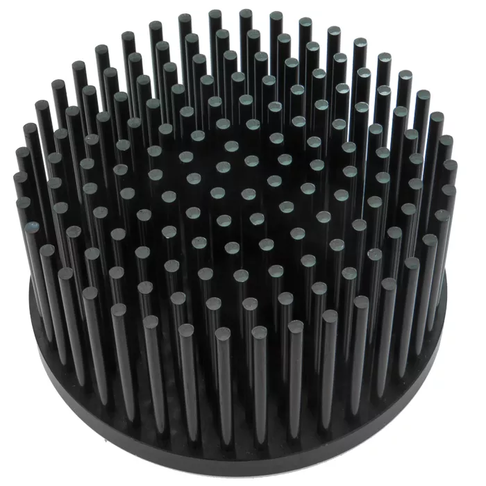
Extrusion Aluminum is another common heat sink manufacturing process wherein aluminum flows plastically under compressive forces into a variety of shapes. Complex 2D profiles can be extruded through a die orifice and is then cut into various lengths. This process does not produce internal porosity that can affect thermal conduction and therefore is capable of producing aluminum heat sinks with higher thermal conductivity than die castings. Aluminum extrusions made from 6xxx alloys offer thermal conductivities in the 200-215 W/mK range. Aluminum extrusions are mostly used to create linear lighting systems for cove lighting, under cabinet lighting, and other architectural lighting installations wherein LED strip lights serve as the light source. Low profile heat sinks with very complex cross-sections can also be made using this process.
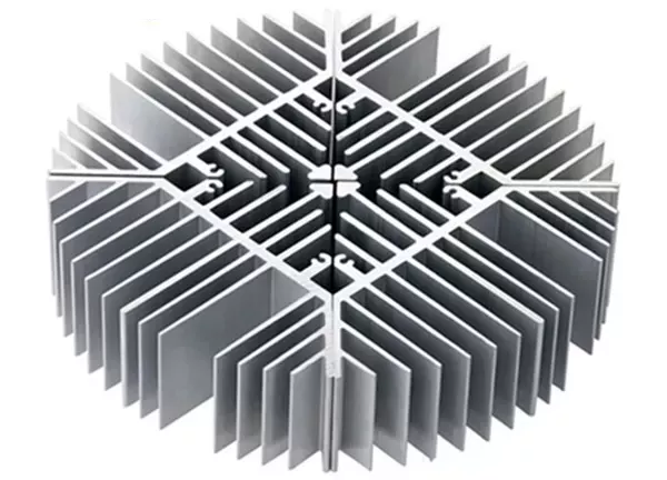
Stamping Aluminum is a cold-forming operation for creating sheet metal parts. Metal stamping is accomplished by insertin
g flat metal sheets into a die and using various metalworking techniques to form the metal into the desired geometry. The metalworking techniques most commonly associated with stamping include punching, blanking, deep drawing, pressing, embossing, bending, and flanging. This process is primarily employed to make stake fins and insert fins. Stamping can expand the scalability of heat sinking solutions from a few watts easily up to several hundred watts. This cost-effective process is capable of producing large-scale, full-sized runs.
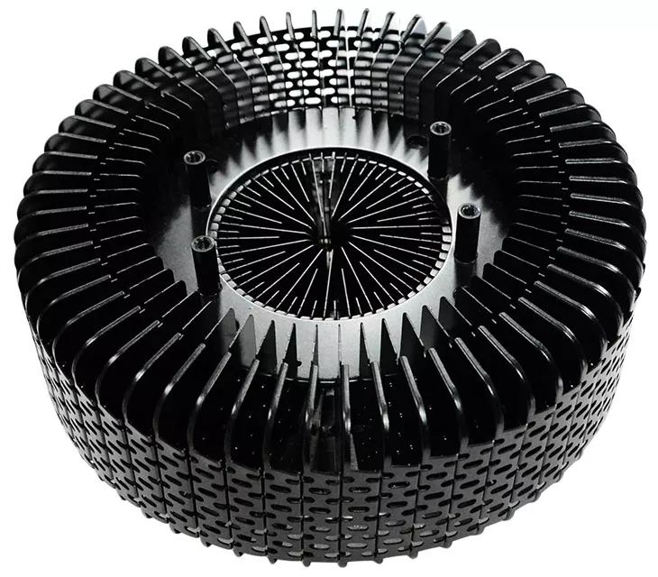
Bonded fin Aluminum heat sinks are designed to maximize fin densities and depth so as to provide a high volume of convective heat transfer. The heat sink is constructed in such a way that a high density array of plate fins are assembled into a grooved base. A bonding agent, which can be a thermosetting thermally conductive epoxy or a solder, hold the plate fins tight in place. Despite the use of thermally improved bonding agent, there’s still interface resistance between the fins and base. Bonded heat sinks are available with a wide range of material and fabrication options. Hybrid heat sinks combining different materials and metalworking processes for the fins and base can be accommodated by this solution. The grooved base can be extruded, die cast or machined. The plate fins can be extruded or stamped. Either aluminum or copper can be used to fabricate bonded fin heat sinks.
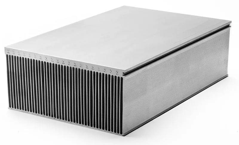
Skived fin heat sinks are carved out of metal blocks. Unlike bonded heat sinks which assembly plate fins into slots on an extruded or machined base and the fins are held in place by a bonding agent, there is no interface resistance in skived fin heat sinks as they’re are constructed from a single piece of aluminum or copper. The skiving process enables a high aspect ratio (taller fins and higher densities). These thermal characteristics allow skived fin heat sinks to deliver high performance thermal management. However, skiving process is not an economically viable solution for mass production of LED heat sinks.
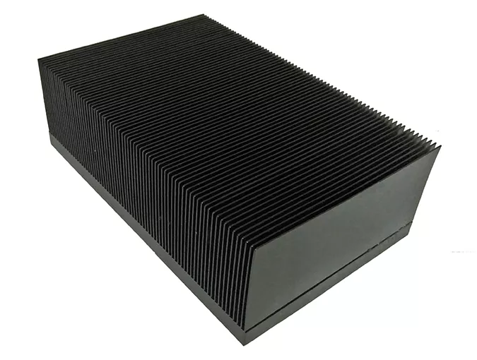
Machined heat sinks are similar to the skived type in manufacturing process except for these heat sinks are machined out of a metal block by gang saw cutting. Both the machining and skiving processes consume raw materials in an unproductive manner and are therefore less frequently used as LED heat sinks. The only good with machined heat sinks are their short lead time for small batches and high thermal conductivity as a result of low thermal resistance throughout the construction.
Don't buy too cheap, the different material of solar street light, choose good quality solar led street light
View detailsRemote Control User Manual of Solar Street Light, Remote Controller, PIR Induction Control Mode, Time Control Mode
View detailsFailures and solutions of solar street lights
View detailsE Series Linear IC Driver DOB Highbay Light, Square Luminous with Looped Optical Lens.
View detailsWHAT IS INTEGRATED ALL IN ONE SOLAR STREET LIGHT? and Components
View details